
Libra WeighTech
Accurate Weighing
Quality Services

A customer calls with a simple question: “I have a 6 wire load cell and my indicator only has four terminals. Will it work?” Or the other way round. Or a replacement load cell arrives with the wrong number of wires and the technician is already on site.
The 4 wire vs 6 wire load cell question comes up constantly, and the answer is rarely “one is better.” Both use the same sensing principle. The difference is two extra wires and what they do. Get them right and your scale stays steady across seasons. Get them wrong and you will chase drift that no recalibration fixes.
Let us walk through it plainly. To see products as you read, browse our load cell and indicator range.
|
|
4 wire load cell |
6 wire load cell |
|
Wires |
Excitation (+ and −), Signal (+ and −) |
Same four, plus Sense (+ and −) |
|
Cable length tolerance |
Fine for short, stable runs |
Better for long runs and temperature swings |
|
Compensates for cable resistance |
No |
Yes, when sense wires are used |
|
Typical use |
Bench, tank and platform scales with short cable |
Truck scales, long cable runs, high-accuracy systems |
|
Cost |
Lower |
Slightly higher |
|
Indicator needed |
4 wire or 6 wire terminals |
6 wire terminals for full benefit; can be adapted to 4 wire |
In one sentence: a 6 wire load cell is a 4 wire load cell with a built-in way to correct for the cable between it and the indicator.
Inside a strain gauge load cell sits a Wheatstone bridge. The indicator sends a steady voltage into it (excitation) and reads a tiny voltage coming out (signal). As load increases, the output rises in proportion.
• Excitation + and −: supply voltage from the indicator to the bridge, typically 5 V or 10 V DC depending on the indicator.
• Signal + and −: the small output voltage, measured in millivolts, that the indicator converts to weight.
• Shield: a drain wire or braid that protects the signal from electrical noise.
The signal is expressed as a ratio of output to excitation (mV/V). That is why wiring quality matters: if the excitation reaching the cell is lower than the indicator thinks it is sending, the weight reading is wrong.
Cable copper has resistance. Over a long run, some excitation voltage is lost on the way, and the loss changes with temperature because copper resistance rises as it heats up. In a 4 wire system the indicator cannot see that loss. It assumes the bridge receives full excitation.
Load cell sense wires fix this. They run from the cell’s excitation points back to the indicator, letting it measure the voltage the bridge actually receives and correct for the difference. Sense wires carry almost no current, so cable resistance barely affects them.
Think of it like this: excitation wires are a water pipe feeding a tank. Sense wires are a gauge at the tank itself, telling the pump how much pressure really arrived, not how much it sent.
In practice, on long cables or where temperature swings widely, a 6 wire connection keeps readings steadier. In Punjab, where a weighbridge cable can run tens of metres under summer sun, that benefit is real.
• The cable run is short, as with bench scales, small platform scales and hopper scales near the indicator
• Temperature around the cable stays fairly stable
• The accuracy requirement is moderate
• The indicator has only 4 wire input terminals
Many reliable workshop and warehouse platform scales run on 4 wire cells for years without trouble.
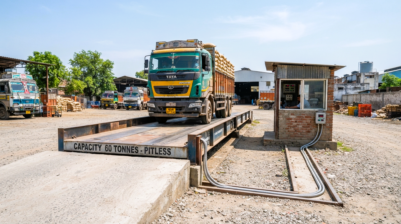
• Truck scales and weighbridges with long cable runs
• Outdoor installations with large temperature swings and sun exposure
• Multi-cell systems where junction box and cable losses add up
• Higher accuracy or legal-for-trade use, where drift is costly
• Systems where cable has been extended or replaced
Wire count is only one part of load cell indicator compatibility. Before connecting anything, compare the datasheets of the cell and the indicator:
1. Wires and terminals: does the indicator have sense terminals?
2. Excitation voltage: the indicator’s output must suit the cell’s rated excitation range.
3. Sensitivity (mV/V): the indicator’s input range must accommodate the cell’s rated output at full load.
4. Bridge resistance: the indicator can drive only a limited number of cells in parallel; check combined resistance against its minimum.
5. Cable type and shielding: use shielded cable suited to the environment.
6. Output type: analog mV/V cells and digital cells use different interfaces and do not mix.
Rule of thumb: if two datasheets do not clearly agree, do not guess. Ask your supplier or technician before powering up.
Generally yes, and this is the question we hear most. If the indicator has four terminals, the usual approach is to join each sense wire to its matching excitation wire at the indicator: sense + to excitation +, sense − to excitation −. The system then behaves as a 4 wire system. You keep the cell but lose cable compensation.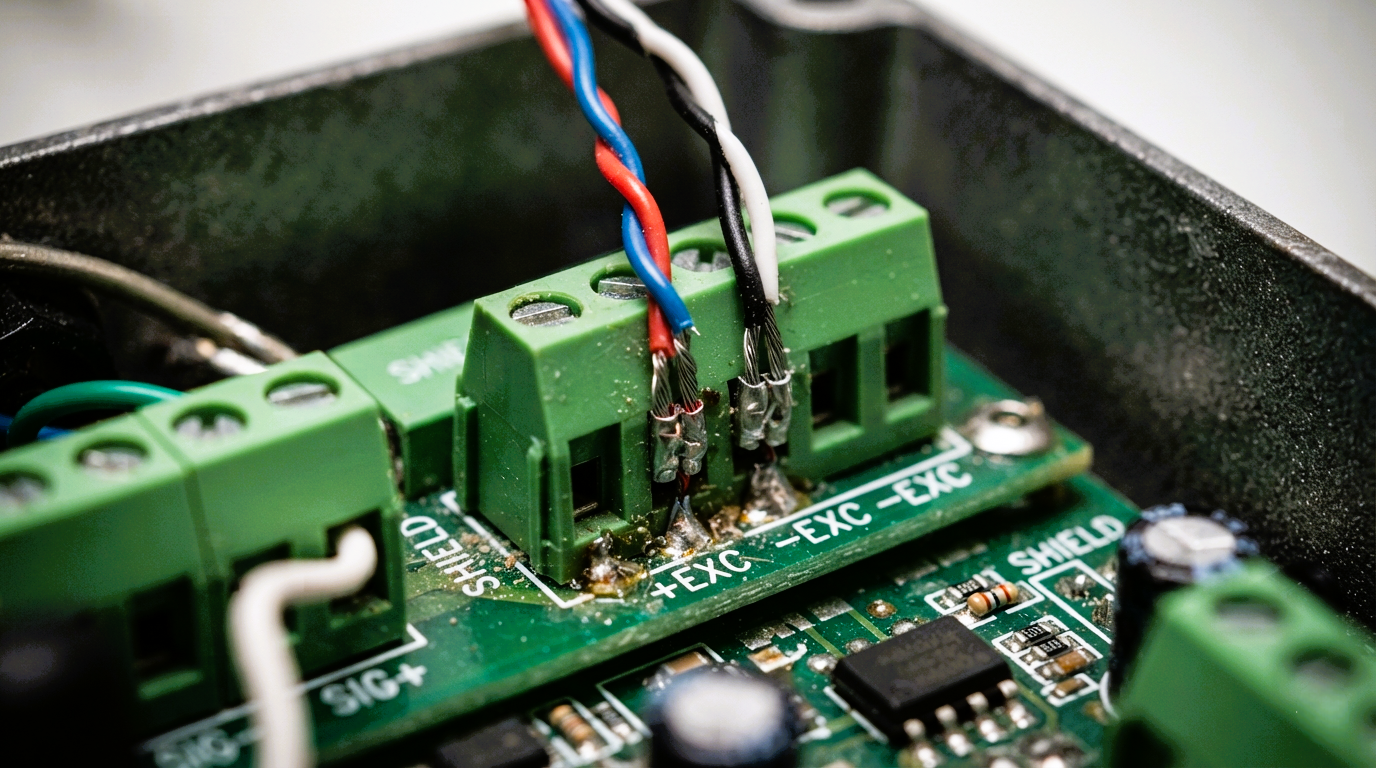
Do not simply cut the sense wires and forget them, and do not join them at the load cell end unless the manufacturer says so, because that defeats their purpose. If you are unsure which wire is which, stop and check the datasheet.
Also yes. Link the indicator’s sense terminals to its own excitation terminals using the jumpers or switch the manual describes. Readings will work, without the compensation benefit.
Swapping a failed cell is one of the most common service jobs. Our service technicians follow steps like these: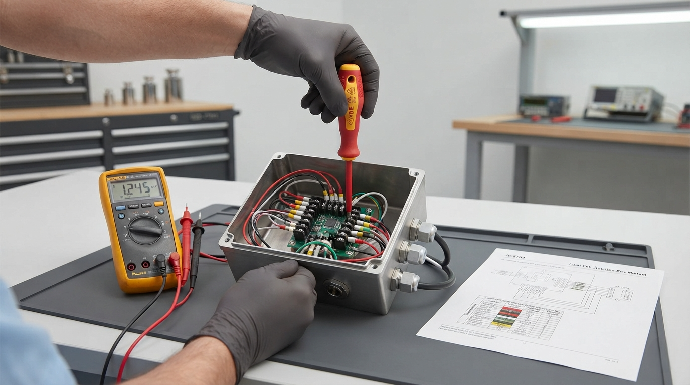
7. Disconnect power and photograph the existing wiring before touching anything.
8. Record the old colour code and where each wire lands.
9. Compare the new cell’s datasheet with the old: capacity, mV/V, impedance, wire count and colours.
10. Do not assume colours match. Colour codes vary between manufacturers. Match by function, not colour alone.
11. Make clean, tight terminal connections with a proper cable gland.
12. Do not cut or shorten the cable unless the manufacturer allows it.
13. Check zero balance and run corner tests.
14. Recalibrate with certified test weights.
A scale showing negative weight under load often has signal wires reversed. One that will not read at all may have excitation or signal wires on wrong terminals, or a damaged cable. If the new cell behaves oddly, our guide to unstable weighing scale readings covers what to check next.
|
Specification |
What to confirm |
|
Conductor count |
4 core for 4 wire, 6 core for 6 wire, plus shield |
|
Conductor size |
Enough cross-section for the run length; thinner wire loses more voltage |
|
Shielding |
Braided or foil shield, grounded as the manufacturer recommends |
|
Jacket material |
Suited to heat, oil, chemicals and sunlight |
|
Temperature range |
Must cover your summer and process temperatures |
|
Length |
Keep original length if the cell is cable-sensitive; avoid unnecessary extensions |
|
Ingress protection |
Match the cell’s rating, with sealed glands and connectors |
|
Routing |
Away from power cables, motors and variable frequency drives |
If a cable must be extended, use a proper junction box with good terminals, not twisted joints with tape. Poor joints are a common hidden cause of drift.
Most wiring problems come from nobody writing anything down. Ten minutes of load cell connection documentation at installation saves hours at the next fault. Keep a record for every scale:
|
Item |
Details to record |
Where to keep it |
|
Load cell make and model |
Capacity, serial number, mV/V |
Folder and junction box label |
|
Wire count and colour code |
Function of each colour, from the datasheet |
Inside junction box lid |
|
Terminal map |
Which wire goes to which terminal |
Photo and printed copy |
|
Indicator settings |
Excitation, sense jumpers, calibration values |
Maintenance file |
|
Cable details |
Length, type, joints or extensions |
Maintenance file |
|
Zero and calibration log |
Dates, test weights, results |
Maintenance file |
Add the date and technician’s name whenever anything changes. For background on specs behind calibration, see our guide on scale capacity vs readability vs accuracy.
• Assuming colour codes are universal. They are not.
• Leaving sense wires disconnected on a 4 wire indicator instead of linking them to excitation.
• Cutting the cable without checking manufacturer guidance.
• Mixing different cell models in one multi-cell system without matching specs.
• Poor terminal connections in humid or dusty junction boxes.
• Running load cell cable beside power or VFD cables.
• Skipping recalibration after replacing a cell or cable.
• Long weighbridge cable runs are common, so 6 wire is often the better choice.
• Summer heat and sun change cable resistance; sense wires and UV-resistant jackets help.
• Monsoon humidity attacks terminals; use sealed boxes and glands.
• Mixed-brand spares are common locally, so datasheet checks matter even more.
• Generator and load shedding spikes stress indicators; good earthing keeps the signal clean.
What is the difference between a 4 wire and 6 wire load cell?
A 4 wire load cell has two excitation and two signal wires. A 6 wire adds two sense wires, letting the indicator compensate for voltage lost in the cable. The extra wires matter most on long cables and in changing temperatures.
What do sense wires do on a load cell?
They measure the excitation voltage actually reaching the cell and feed it back to the indicator, which corrects for cable resistance and temperature effects.
Can I connect a 6 wire load cell to a 4 wire indicator?
Generally yes. Join each sense wire to the matching excitation wire at the indicator. You lose cable compensation but the cell works. Check the datasheets first.
Can I connect a 4 wire load cell to a 6 wire indicator?
Yes. Link the indicator’s sense terminals to its excitation terminals as its manual describes.
Is a 6 wire load cell more accurate than a 4 wire?
Not by itself. A 6 wire connection gives better system stability when cables are long or temperatures change.
Are load cell wire colours the same for every brand?
No. Always match wires by function using the datasheet.
Can I extend or shorten a load cell cable?
Only if the manufacturer allows it. Make extensions in a proper junction box, and recalibrate after any change.
Not sure whether your scale needs 4 wire or 6 wire cells, or whether a replacement suits your indicator? Send us the make, model and photos of your junction box and the team at Libra Weightech will confirm the match. Request a quote or contact our service team.